Background
I've been wanting experiment with digital electronics, in the same vein of Ben Eater's "8-bit breadboard computers" video serie. And for that, I am going to need some sort of EEPROM where to store machine code.
Hardware
Arduino MEGA
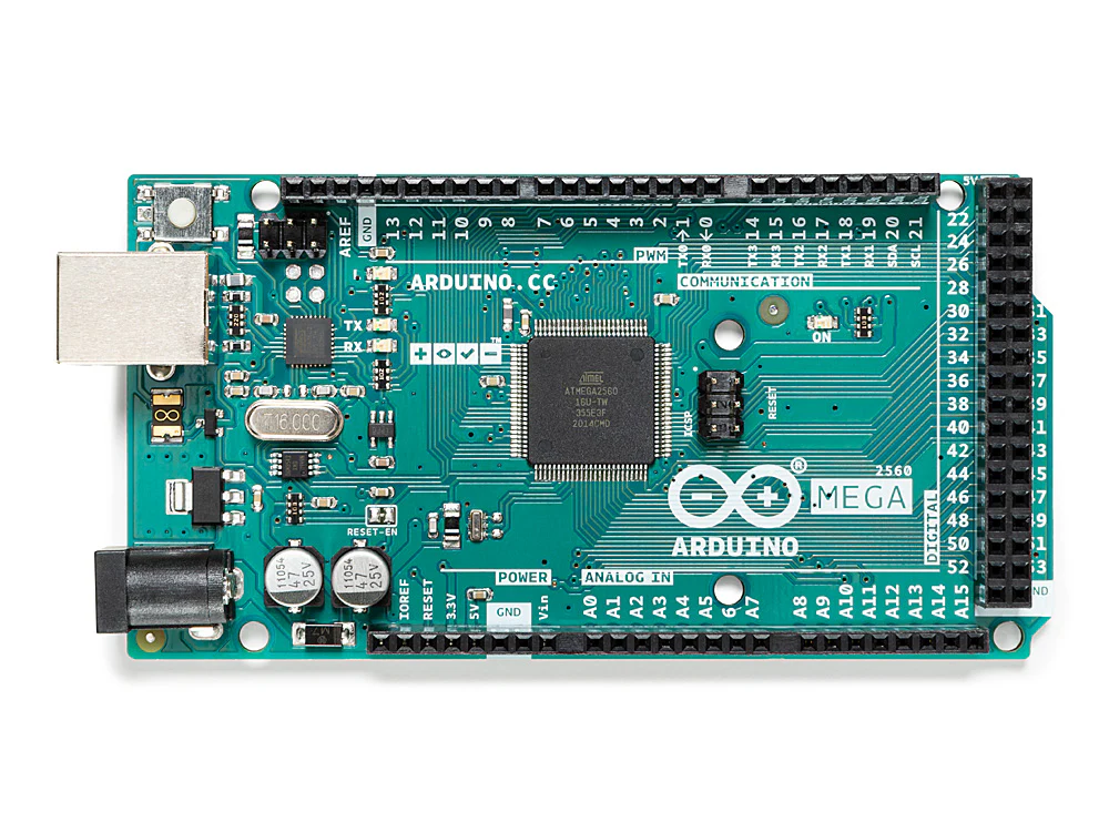
An Arduino UNO was first entertained as a possible solution for this. But later timing and pin count requirements (more than 16 pins) made it a bit convoluted. Since I would need to do Arduino Port programming with bitshifters. And hoping that after all that it will still comply with write timings.
So I ended up choosing an Arduino Mega, a board with more than enough GPIO pins for this task.
The EEPROM
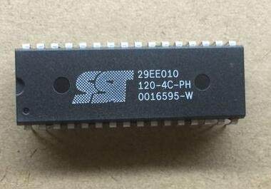
I found a SST29EE010 on an old motherboard.
My initial happiness vanished as soon as I discovered that Ben Eater's EEPROM programmer script won't work right out of the box.
Turns out that it has some sort of software write protection (SDP). Which complicates writting to it.
A W29C020 can also be used in the same way.
Theory
I found this video useful in explaining what this EEPROM memory protection is. And how to practically disable it with custom software and an Arduino.
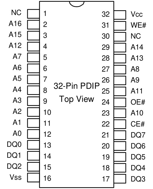
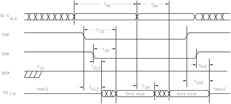
EEPROM Read Protocol
- Controlled by CE# and OE# (# means active low)
- both have to be low/active
- Seems pretty normal, at least compared to 28C256 which Ben Eater used.
| T_RC | read cycle | 90 | ∞ |
| T_AA | addr access | - | 90 |
| T_CE | chip enable | - | 90 |
| T_OE | output enable | - | 40 |
EEPROM Write Protocol
- Writes have to follow a handshake part of SDP protocol.
- JEDEC standard Sofware Data Protection (SDP) protocol.
3-byte load sequence for SDP
eeprom[0x5555] = 0xAA;
eeprom[0x2AAA] = 0x55;
eeprom[0x5555] = 0xA0;
- 1-byte load cycle to a page buffer
- internally controlled write cycle
- A0-A6 are used for page writes
- A15-A16 do not matter at all on
SDPcommands - Any byte not loaded with user data will be written to FF
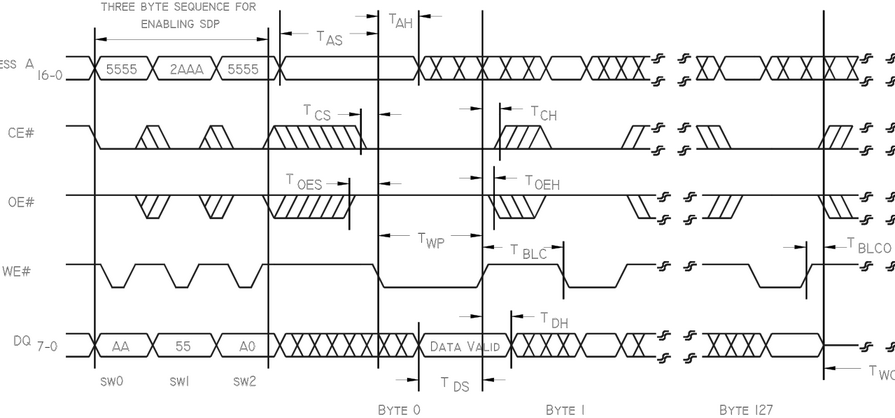
- address is latched at falling edge of #WE
- data is latched at raising edge of #WE
- Said protocol can be disabled. Enabled on EEPROMs found.
Detour: borring an Arduino.
While I started working on this I did so with an Arduino UNO using bitshifters. After failing miserable. And worst of all not knowing if it was my code or the physical limitations of my setup the cause of failure.
I opted for sacrifice a 3d printer to get an Arduino Mega from it to try without the register shifters.
In the process I learned how to dump the binary flash content of an arduino to a file with avrdude.
$ avrdude -D -p atmega2560 -c wiring -P /dev/ttyACM0 -U flash:r:flashdump.bin:r -v
Real world challenges
- Electronic Interference: turns out that if I cradle in my hand the Breadboard, including the Arduino, in my hand it will create some sort of noise that will affect readings.
- Bad Wiring: We are going to be using +24 GPIO pins from the Arduino to the EEPROM. Plus some that should be hardcoded to LOW, like CE. Double check wiring positioning and cable health.
- Ground all INPUTS not being used: As mentioned before, this is particularilly important for address inputs not used.
- Write code only for testing:
- code to read serially (without using port programming) ensure the sanity of my port programmed code
It works!
So, after some weird lectures and even weirder succesful-ish writes. I fixed some wirings and…it works!
000:  41 42 43 44 45 46 47 48   01 02 04 08 10 20 40 80
010:  7f bf df ef f7 fb fd fe   00 ff 55 aa 30 31 32 33
020:  ea ea ea ea ea ea ea ea   ea ea ea ea ea ea ea ea
030:  ea ea ea ea ea ea ea ea   ea ea ea ea ea ea ea ea
040:  ea ea ea ea ea ea ea ea   ea ea ea ea ea ea ea ea
Which is exactly the test pattern given by TommyPROM. Meant to be a non random pattern easily discerned from noise.
byte data[] = {
    'A',  'B',  'C',  'D',  'E',  'F',  'G',  'H',  0x01, 0x02, 0x04, 0x08, 0x10, 0x20, 0x40, 0x80,
    0x7f, 0xbf, 0xdf, 0xef, 0xf7, 0xfb, 0xfd, 0xfe, 0x00, 0xff, 0x55, 0xaa, '0',  '1',  '2',  '3'
};
Source
This is the final code (for now) that I use to write the EEPROM using an arduino Mega heavily based on TommyPROM version of Ben Eater's code. You might find a more recent recent version here.
#define NBLOCKS 5
#define WE 4
#define OE 3

// Port Registers:
// <- A = data
// -> C = addr lower
// -> L = addr higher

byte data[] = {
    'A',  'B',  'C',  'D',  'E',  'F',  'G',  'H',
    0x01, 0x02, 0x04, 0x08, 0x10, 0x20, 0x40, 0x80,
    0x7f, 0xbf, 0xdf, 0xef, 0xf7, 0xfb, 0xfd, 0xfe,
    0x00, 0xff, 0x55, 0xaa, '0',  '1',  '2',  '3'
};

void setAddress(word addr) {
  DDRC = 0xff; // 1 = OUTPUT
  DDRL = 0xff; // 1 = OUTPUT
  PORTC = (addr >> 0) & 0x00ff;
  PORTL = (addr >> 8) & 0x00ff;
}

void writeEEPROM(int addr, byte wdata) {
  digitalWrite(OE, HIGH);
  setAddress(addr);
  digitalWrite(WE, LOW);
  DDRA = 0xff; // 1 = pinMode = OUTPUT
  PORTA = wdata;
  delayMicroseconds(1);
  digitalWrite(WE, HIGH);
}

byte readEEPROM(int addr) {
  byte rdata = 0;
  DDRA = 0x00; // 0 = pinMode = INPUT
  setAddress(addr);
  digitalWrite(WE, HIGH);
  digitalWrite(OE, LOW);
  rdata = PINA;
  digitalWrite(OE, HIGH);
  return rdata;
}

void setup() {
  digitalWrite(WE, HIGH);
  pinMode(WE, OUTPUT); digitalWrite(WE, HIGH);
  pinMode(OE, OUTPUT); digitalWrite(OE, HIGH);

  DDRC = 0xff; // 1 = OUTPUT
  DDRL = 0xff; // 1 = OUTPUT

  Serial.begin(57600);
  while(!Serial);

  /* Serial.print("\nDisabling SDP..."); */
  /* disable_sdp(); */
  /* Serial.println(" done"); */

  // Dump
  printContents();
  // Programming
  Serial.print("Programming ... ");
  for (word address = 0; (address < sizeof(data)); address++) {
    // Wait after each TBLCO (Byte Load Cycle Time)
    if (address != 0 && address % 128 == 0) {
      while (readEEPROM(address-1) != readEEPROM(address-1)) {
        delayMicroseconds(100);
      };
    }
    writeEEPROM(address, data[address]);
  }
  // Padding
  for (word address = sizeof(data); address % 16 != 0; address++) {
    writeEEPROM(address, 0x00); // NOP = 0x00
  }
  Serial.println("done");
  delay(500);
  // Validation
  Serial.print("Validating...");
  byte okvalidation = 0;
  for (word address = 0; address < sizeof(data); address++) {
    if (readEEPROM(address) != data[address]) {
      okvalidation = 1;
      break;
    }
  }
  if (okvalidation != 0) {
    Serial.println("FAIL");
  } else {
    Serial.println("OK");
  }
  // Dump
  printContents();
}

void loop() {
}

void printContents() {
  for (int base = 0; base <= (NBLOCKS * 127)+1; base += 16) {
    byte bdata[16];
    for (int offset = 0; offset <= 15; offset += 1) {
      bdata[offset] = readEEPROM(base + offset);
    }
    char sbuf[80];
    sprintf(sbuf, "%03x:  %02x %02x %02x %02x %02x %02x %02x %02x   %02x %02x %02x %02x %02x %02x %02x %02x",
            base, bdata[0], bdata[1], bdata[2], bdata[3], bdata[4], bdata[5], bdata[6], bdata[7],
            bdata[8], bdata[9], bdata[10], bdata[11], bdata[12], bdata[13], bdata[14], bdata[15]);
    Serial.println(sbuf);
  }
}

void disable_sdp() {
  digitalWrite(OE, HIGH);
  DDRA = 0xff;
  setByte(0x5555, 0xaa);
  setByte(0x2aaa, 0x55);
  setByte(0x5555, 0x80); // 0x80
  setByte(0x5555, 0xaa);
  setByte(0x2aaa, 0x55);
  setByte(0x5555, 0x20); // 0x20
  DDRA = 0x00;
  delay(10);
}

void setByte(int addr, byte data) {
  setAddress(addr); // digitalWrite(OE, HIGH);
  PORTA = data;
  delayMicroseconds(1);
  digitalWrite(WE, LOW);
  delayMicroseconds(1);
  digitalWrite(WE, HIGH);
}
Resources
- Arduino UNO https://github.com/TomNisbet/TommyPROM
- uses bitshifters
- alternative code for Ben Eater setup
- Teensy 3.5 https://github.com/slu4coder/SST39SF010-FLASH-Programmer
- teensy is waaaay faster than UNO/MEGA
- uses has a clock of 120MHz, while my Arduino's have 16MHz.
- has enough GPIO ports to NOT use bitshifters
- does NOT use port programming
New Feature: Multi page writting.
Today trying to write data to a ROM. Ended up hitting a bug that I missed. That is that it didn't support writting to multiple pages. Since each page is of 128 bytes. I added a pause (TBCLO) after each page write.
Seems to work :)