Components
Digging through old projects I took a stab to try to make 2 different things work together.
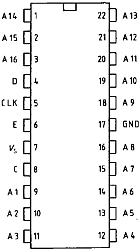
- A two digit 7-segment display controled by an
SDA2131display driver. Found already wired together on a pcb board in an old pc.
| EN | CLK | DATA | Vss | GND | x | x |

- A
DHT11temperature and humidity sensor. That I bought a while back, when I was turning on and off leds with an arduino.
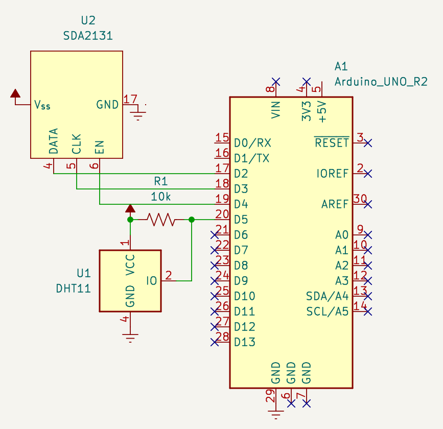
Wiring

Implementation
Thanks to its datasheet and someones arduino code to control it I was able to understand how make it work.
For SDA2131 basically you just send 16 bits of DATA representing if a segment should be on or off at a given CLOCK time.

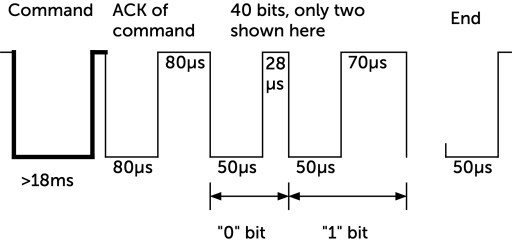
For DHT11 is simpler from the Arduino point of view since there is a library already for it. But it's a similar protocol (albeit more a synchronous and time based protocol) thanks to an embedded microcontroller inside the sensor.

Challenge
I wasn't obvious how to convert from a binary representation of a number from DHT11 to a list of bits of segments. I ended up decomposing the number in his digits and then mapping with an array of predefined bits was enough for this (see WriteNum()).
Code
#include <dht.h> // DHTlib

#define DELAY 2000

#define PIN_DHT 5
#define PIN_ENA 4
#define PIN_CLK 3
#define PIN_DAT 2

byte num2bits[] = { B10110111, B00100100, B01110011, B01110110, B11100100, B11010110, B11010111, B10110100, B11110111, B11110110 };
bool flip = false;
dht DHT;

void setup() {
  pinMode(PIN_ENA, OUTPUT);
  pinMode(PIN_CLK, OUTPUT);
  pinMode(PIN_DAT, OUTPUT);
}

void writeNum(byte n) { writeNumRaw((n > 99) ? 0 : n); }
void writeNumRaw(byte n) {
  digitalWrite(PIN_ENA, HIGH);
  shiftOut(PIN_DAT, PIN_CLK, LSBFIRST, num2bits[n % 10]); // right
  shiftOut(PIN_DAT, PIN_CLK, LSBFIRST, num2bits[n / 10 % 10]); // left
  digitalWrite(PIN_ENA, LOW);
}

void loop() {
  flip = !flip;
  int chk = DHT.read11(PIN_DHT);
  if (flip)
    writeNum(DHT.temperature);
  else
    writeNum(DHT.humidity);
  delay(DELAY);
}